Audio over the MCA Bus

Driving Linear Amp Input Node

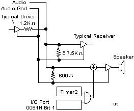
The audio subsystem is a speaker driven by a linear amplifier.  The linear amplifier input node can be driven from the following sources: 

Tone Generator (timer 2) output Enabled using bit 1 of I/O port 0061h set to 1.  (For information about timer 2 see Programmable Timers.) 

  • GATE 2 is controlled by bit 0 of System Control Port B. 
  • CLK IN 2 is driven by a 1.193-MHz signal. 
  • CLK OUT 2 has two connections. One is to input port hex 0061, bit 5. CLK OUT 2 is also logically ANDed with port hex 0051, bit 1 (speaker data enable). The output of the AND gate drives the "Audio Sum Node" signal. 

  •  


    System Channel, using the 'audio sum node' signal. 

    Audio Subsystem Block Diagram

       Each audio driver must have a 1200-ohm source impedance, and 
    a 7.5-kilohm or greater impedance is required for each audio 
    receiver. Volume control is provided by the driver.  Output level is a 
    function of the number of drivers and receivers that share the 
    AUDIO line. 

    The logic ground is connected to AUDIO GND at the amplifier. 

    Single channel analog audio signal . Synthesized voice or music generated on a Micro Channel adapter can be routed as a complex analog waveform directly to the amplifier and speaker inside the computer. The Micro Channel allows expansion cards on the channel to exchange and independantly process audio signals.
     

    Audio Signal Group
       Consists of an analog voltage sum node and an audio ground.

    Audio Sum Node (Signal pin B02)
       Used for communication of audio signals between devices on the bus or to the system speaker.
      Frequency range 50Hz to 10kHz, +/- 3db. Maximum analog noise level is 50mV. Analog signal amplitude is 2.5V peak-to-peak with a DC offset of 0 +/- 50 mV.

    Audio Gnd (Signal Pin B01)
       Used as the audio ground return signal.

    9595 Main Page