95 RAID Bay
Install RAID Bays
RAID Bay PCBs 
  RAID Bay PCB
  Bottom RAID Bay PCB
  Jumpers on PCBs
  TL-SCSI285
Power Microswitch
Remove RAID Bay
RAID without Trays and Bays


Bays Available 
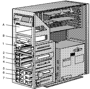


1. Find the bay in which you plan to install the drive assembly.
     If a drive assembly is already installed in the bay you plan to use, remove the drive assembly as described in steps 3 and 4 of Removing Internal Drives. 
Note:  The figures that accompany these steps show the installation occurring in bay 1.  These instructions also apply to bays 2 through 7. 

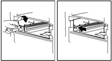
2.  Prepare the bay for installation of the drive assembly: 

   a. Insert a small coin into the slot of the small knob located on the left-hand side of the bay.  (Do not use more than light pressure to do this! You can snap one "ear" off of the knob. Personal experience) 
   b. Turn the knob clockwise, one-quarter (1/4) of the way. 
   c. Slide the knob to the left. 
    d. Continue with the next step. 

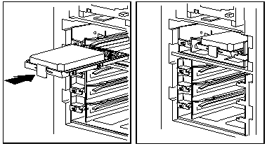
3.  Install the hard disk drive assembly into the bay:

  a. Position drive assembly so the connector is facing rear of server. 
  b. Align tray with guides, and slide the drive assembly into the bay. 
  c. Slide the knob to the right until it clicks into place. 


RAID Bay PCB 61G3843

RAID Bay Bottom PCB  61G3843

IC1 Linear Tech LTC1155
IC2 TI TL-SCSI285N
P1 4 pin Drive power conn
P2 header to microswitches
P3 SCSI ID header
RP1-4 Resistor Networks
Q1,2 IRFZ48 MOSFET

  The components differ only in the lack of termpacks and SCSI ID circuitry on the bottom PCB and the SCSI ID jumper on the top PCB. The single drive RAID bay uses the top PCB 61G3843.

Jumper Settings for Top and Middle PCBs
 Top card has a jumper on the left pair, the middle has a jumper on the middle pair.

TL-SCSI285slvs065f.pdf (82 kb) 
Comparing Bus Solutions  slla067.pdf
   The TL-SCSI285 is a low-dropout (0.7-V) fixed-voltage regulator specifically designed for SCSI alternative 2 active signal termination. The TL-SCSI285 0.7-V maximum dropout ensures compatibility with existing SCSI  systems, while providing a wide TERMPWR voltage range. At the same time, the ±1% initial tolerance on its 2.85-V output voltage ensures a tighter line-driver current tolerance, thereby increasing the system noise margin. 
    The fixed 2.85-V output voltage of the TL-SCSI285 supports the SCSI alternative 2 termination standard, while reducing system power consumption. The 0.7-V maximum dropout voltage brings increased TERMPWR isolation, making the device ideal for battery-powered systems. The TL-SCSI285, with internal current limiting, overvoltage protection, ESD protection, and thermal protection, offers designers enhanced system protection and reliability. 
   When configured as a SCSI active terminator, the TL-SCSI285 low-dropout regulator eliminates the 220- and the 330- resistors required for each transmission line with a passive termination scheme, reducing significantly the continuous system power drain. When placed in series with 110- resistors, the device matches the impedance level of the transmission cable and eliminates reflections. 

Microswitch Configuration

The switch is marked L119 4A 250VAC, 311SM702-T made by MICRO
Black wire goes to the left terminal "B", yellow wire goes to "Y". 

   The lever rests on the stop. If you have the lever below it, then your switch will stay "on" reguardless of how you turn the blue knob on the Hot Swap (HS) tray. The spring rides on top of the lever, forcing it down.


Remove RAID Bay

Single drive bay shown, three drive bay similar.

   Both the three drive and single drive RAID bays have the spring catch on the right side of the bay, facing to the side wall. So to remove a bay, remove the SCSI cable, and unplug the power cable from the PSU. Press in the catch and push the bay out of the DASD structure. 


RAID without Bays 'n Trays
From Peter 
    I used a 7-drop cable from an 9585 on the first (inner) channel of the Passplay. Installed six HDs and one CD-ROM drive with the IDs running 0 - 6 ... and the Passplay did recognize only the "bays 1 - 4" which correspond with the drive IDs 0 - 3 (0 is the CD-ROM, IDs 1 - 6 are HDs). 
   Then I plugged the cable to the second (rear) channel - and it did show only the bays 5 - 7 (lower triple) - but shows the drive infos for the devices installed at IDs 1 - 3 and not ID-0 (the CD-ROM) !!. After that I set the drives to 0-1-2-3 (CD, HD1, HD2, HD3) connected to inner channel and 1-2-3 (HD4, HD5, HD6) connected to the outer channel using a second cable. 
    The drive cages from a 9595A "Array" machine are designed to send the IDs 1, 2 and 3 - given that the drives are wired properly with using the thin "drive addressing cable".  (Ed. that's part of the drive tray) 
    One cage in the top 5.25" bay, one in the lower 5.25" bay and using the proper "server 95 internal cables" result in the IDs 1,2,3 for the top cage, 5,6,7 (!!) for the lower cage (and ID-0 for the CD-ROM in the single Half Height 5.25" bay). See the table below for some "visual aid" on the SCSI-ID confusion. 
      So obviously the two "channel" connectors are predefined, the first connector uses the IDs directly with ID2 fixed masked to "0", while the second connector has the ID2 bit fixed set to "1" here. 

This leads to the following dependency: 
421 = Binary ID-values            | Bay # | 
000 = ID-0 = CD-ROM               |   1   | 
001 = ID-1 = Top Cage,    drive 1 |   2   | 
010 = ID-2 = Top Cage,    drive 2 |   3   | 
011 = ID-3 = Top Cage,    drive 3 |   4   | 
101 = ID-5 = Bottom Cage, drive 1 |   5   | 
110 = ID-6 = Bottom Cage, drive 2 |   6   | 
111 = ID-7 = Bottom Cage, drive 3 |   7   | 
 

 Attention !! 
   These "IDs" in the list above used here are the ones the controller "sees". Not the ones that are really represented through the device SCSI-ID jumpering. ID-7 under normal circumstances is used for the SCSI controller itself - and in fact the "seen" IDs seem to be remapped somehow. See the binary values to explain the dependencies between position and ID sent back to the controller. 
   This list proves that the ID4 bit is used to differ between "upper" and "lower" triple pack. 

9595 Main Page