|
LED Symptom Index after
POST
I got this info along with a 4033 from Russ Blakeman down in Kentucky. LED Symptom Index After Post (IBM 4033) Power Print Symptom On On Functioning OK. Go to Printer Ports Test On Blink Problem w/LAN or 4033. See LAN Check On Off Replace Op Panel Board. If problem reoccurs, replace the 4033. Off On Power LED may be burnt out. Replace Op Panel. Off Blink Replace Op Panel Board. Re-run POST. Off Off Check outlet or ac adapter. NOTE: You might test
the Operator Panel Board. Who has spares anyways?
Printer Ports Test Complete the following steps for your parallel port. 1. Disconnect the adapter s ac power cord from the electrical outlet. 2. Remove all interface cables. 3. Plug the printer wrap plug into the parallel port. 4. Plug the adapter s ac power cord into an electrical outlet. 5. Press and release Reset button. The following sequence should occur: a. The Power LED turns On solid. b. The Print LED: 1) Blinks several times within approximately 3 to 4 seconds 2) Turns Off for up to 10 seconds 3) Blinks continuously in a pattern of two blinks, a pause, then two blinks. Repeat Step 5 to test the serial port. Fail
Pass
LAN Connection Check 1. Disconnect the adapter s ac power cord from the electrical outlet. 2. Remove all interface cables from 4033 except on Models -002 / -012. 3. Configure the adapter for the LAN wrap test as follows: 4033-001 and 4033-011: Attach LAN cable to 4033, but do not connect it to the network. (For type 3 cable applications, an adapter is attached at the receptacle end.) 4033-002 and 4033-012: There is no wrap test 4033-003 and 4033-013: Place the selector switch into position 2. With the T-connector removed, place a 25 ohm BNC terminator cap (P/N 71F1168) on the BNC connector. 4. Plug adapter s ac power cord into an electrical outlet. The following sequence should occur: a. The Power LED turns on solid. b. The Print LED: 1) Blinks several times within approximately 3 to 4 seconds 2) Turns off for up to 30 seconds 3) Turns on solid. Fail
Note: If the 4033 is replaced, you must delete all associations after removing it from the LAN. When a replacement 4033 is connected to the LAN, you must perform the configuration steps and establish new associations. 4033-002 and 4033-012: Replace the adapter
assembly.
4033-003 and 4033-013: Go to Power Supply Voltage Checks. Pass
Operator Panel Testing 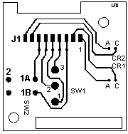
1. Note whether the power LED is on or off. 2. Disconnect the adapter's ac power cord from the electrical outlet. 3. Disconnect the interface cable from the LAN. 4. Remove the top cover screws and tip the cover back. If the power LED was On at the start of the proceedure, go to Step 7. 5. Plug the adapter's ac power cord into an electrical outlet. 6. Check the voltages on CR2: Connect red lead to A, black lead to C (gnd). Voltage should be between 1.6 and 3.0v DC. If voltage is correct and the power LED does not turn on, replace the operator panel board. See "Operator Panel Replacement". If voltage is not correct, replace the 4033. Note: If the 4033 is replaced, you must delete all associations after removing it from the LAN. When a replacement 4033 is connected to the LAN, you must perform the configuration steps and establish new associations. 7. Unplug the adapter's AC power cord from the electrical outlet. 8. Disconnect the operator panel board connector. 9. Check for continuity: a. With the selector switch (SW1) positioned toward the J1 connector, test that points 2 and 3 show continuity, points 1 and 2 are open. b. With SW1 positioned away from the J1 connector, test that points 1 and 2 show continuity, points 2 and 3 are open. c. With the leads touching the two active poles of the reset button SW2) (1A and 1B on image), there should be continuity when the button is pushed. If the button is not pushed, 1A to 1B should be open. FAIL If continuity is not correct in any of the above, replace the operator panel board. PASS If all these tests are OK,
replace the 4033.
Power Supply Voltage Checks Connect ac adapter to outlet. Check for +5V dc and +12V dc on the power supply connector. NOTE: US Models -001, -002, -011 and -012 have only +5V. FAIL Check ac input to PS. If ac input is good, replace power supply. PASS Go to Operator Panel Testing Operator Panel Replacement 1. Remove the four top screws. 2. Tip top cover back and remove the two operator panel mounting screws. 3. Disconnect the operator panel cable. Software and Printer Checks Printer Checks
LAN Checks
|