|
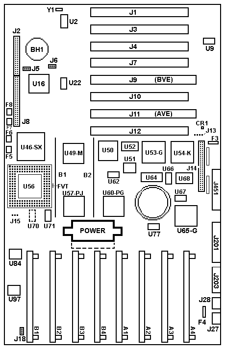
U70 solder pads for another oscillator. Possibly a different cpu speed? Like 25MHz? J15 Three pin header for choosing between 25 and 33 MHz? J13 is for what??? FVT is what? Small outline- Not big enough for a normal header. Not sure. Maybe something to switch between an ODP and ODPR? Need to test where the leads go... rd9585a.exeDiagnostic Diskette v1.11 1994-03-17 M71g1402.exe Reference Diskette v1.11 1993-01-26 postbios.exe BIOS Flash Update v1.11 1993-04-30 What about this BIOS update?
The PS/2 Server 85 was announced September 21, 1992, and was positioned to replace the PS/2 Model 80. Features
EE Floppy Support
Memory The 85-xXx supports a maximum of 64MB of parity memory. All 64MB is addressable by DMA. 2MB, 4MB and 8MB 70ns parity memory SIMMS are supported. Mixed SIMMs Permitted
What is ECC-P?
For more on this fascinating subject, go HERE
ASCII Terminal The IBM PS/2 Model 85 contains a console select utility that allows systems console operations to be performed by an ASCII terminal via the system asynchronous communications port (serial port) preinstalled on the system hard disk. If this option is selected, an ASCII terminal must be connected to the serial port at the time of selection. Onboard SCSI From Peter The onboard SCSI of the 95xx is often refered as "Spock-Prime" - and is (almost) identical to the later SCSI with cache ... with the exception of the cache, which it hasn't got. From the design it is *very* similar to the short SCSI without cache, which has an 80C188-16 as well. The SCSI microcode however is part of the machine BIOS stored in a single small 16-bit PLCC Eprom if I remember correctly. There is a part of the SCSI code also included in the IML. This adapter can be found on the 9556/9557, the "Bermuda" 9576/9577 - and the "small" 9585-0Xx. If you look closely at the 9585-xXx planar you will find some SMD transistor "of the bigger kind" and some stuff that looks like "auto-termination". In addition the onboard SCSI adapter of the "Spock-Prime" is described as "SCSI-2 compliant" ... which extends on the command set in the first place, the enhanced SCSI translation and on the electric interface as well I think. But not on the speed of course, which is 5 MB/s SCSI-1 standard. But How Late?
Uh ... more related to the short SCSI w.o. cache - but nontheless limited to <1GB IML drive. They must have used the old microcode and the BIOS doesn't support it either. There was a POSTBIOS upgrade available for the -xXx - which screws the -xNx and -xKx to crap. But as far as I recall it does not change this misbehaviour. I had that back in '94 or so: customer wanted bigger HDs and bought 1.08GB DPES ... installed IML - seemed to work until you'd switched off and cold-started the -0XA. After that you got an IML-error. No Way. IBM confirmed that the -xXx is not over-1GB capable. Only way to leave a smaller IML HD in the machine. Return Fire
I tend to believe empirical results.
|
 o
o