|
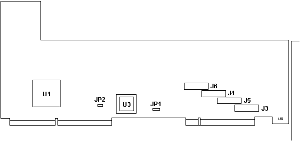
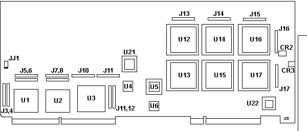
The multiprocessor bus-to-PCI bridge is a special adapter that physically plugs into two sockets, one on the multiprocessor bus and one on the PCI bus. The circuitry on this card controls the movement of data between the processor complexes, memory cards and the I/O adapters on the Micro Channel and PCI buses. It implements a split bus design so that during slower I/O operations the multiprocessor bus can be made available for processor to memory transfers without having to wait on the I/O transfer. PCI Bridge Card FRU 75H9141
IPB Bridge card
JP1 is a three pin header. 1-2 is Primary bridge. 2-3 is Secondary bridge.
PCI Bridge Card FRU 76H7134 Date
of 94
JJ1 Primary 1-2 (bottom) Secondary 2-3 (top)
SUBJECT: INTERMITTENT HANGS - SERVER PC720(8642) SYMPTOM:
PROBLEM ISOLATION AIDS:
FIX:
Bridge card 75H7667 (fru Part Number 71G0694) requires J24 pins 1+2 to be Short circuit ( ie. the 2 pins of J24 nearest the back of the machine.) REASON :
|

