3550 Power
PSU Specs (FRU
49G2688)
115v/4A, 220v/2A
+5v 11.0A
+12v 2.4A
-12v 0.3A
8-20v 2.5A
Total 147.4W Max
The 8 to 20v is for charging the 700/720 battery
Remove the Power Supply
This threw me for a loop, but I eventually pegged onto
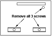
it. Undo the three captive thumbscrews at the rear of the 3550, remove
the bezel. Remove the top by pushing it forward about an inch, then lift
up (like a 50/70/90). Unplug any device in the 5.25" bay. Pull off
the right side of the spring bezel by pulling straight out. Unplug P1 and
P2 on the right side of the systemboard. Move all three cables to the front
so you can pull them through the enclosure.

IMPORTANT! Remove the two
phillips screws along the lower outer edge of the PSU (on the die cut extensions)
and remove the single phillips screw fron the upper right corner above
them. This single screw will stop you!

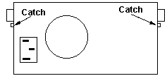
Look at the back of the case. Notice the two black angles
sticking out, and immediately below them, a catch. Lift up on each catch
and slide the PSU out of the case. It's loose enough so you can undo one
side, push the PSU out a bit, then undo the other catch, then slide the
PSU out.
Opening the PSU
See above to remove the PSU from the case. Now sit and
try to figure out howthehell is this going to work? A VERY important point.
Look at the "step" right above the cable outlet. See that small phillips
screw right next to the inner vertical edge? You must remove that screw,
because it fastens a heatsink from the PCB to the case. Remove the two
T-15 security TORX at the front lower edge of the PSU.
Look at the upper rear edge of the PSU case. Note that
the upper piece of the PSU case is hooked under the back edge. Pry the
upper piece forward until it clears the retaining lip. Now rotate the upper
piece forward on the wire bundle for the power conductors only about an
inch. Now twist the cover towards the side of the wire bundle so it can
uncover the PSU guts.
Power Systems Checkout
If the “power good” light is not on and if the power-supply
fan is not running, check the power cord for continuity and proper installation.
If the power cord is not the problem, either the power
supply is defective or another component is defective and is causing the
power supply to shut off. To verify that the power supply is operating
correctly, do the following:
1. Power-off the 3550 Expansion Unit and disconnect the 3550 Expansion
Unit power cord.
2. Remove all power supply connectors (power supply connector P1, P2
and drive connector 1) from the system board of the 3550 Expansion Unit
and SCSI device.
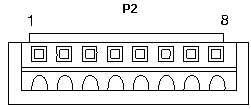
3. On power supply connector P2, short-circuit pin 4 to pin 6 and short-circuit
pin 7 to 8.
4. Connect the 3550 Expansion Unit power cord.
5. Check the power supply voltages using the figures on the next page.
Drive Connector
1
Standard 4 pin molex
|
Pin
|
Signal
|
V dc Min.
|
V dc Max.
|
|
1
|
+12 volts
|
+11.52
|
+12.6
|
|
2, 3
|
Ground
|
|
|
|
4
|
+5 volts
|
+4.8
|
+5.25
|
If any of the voltages are not correct, replace the power supply.
If all voltages are correct, the power supply is working
properly. Another 3550 Expansion Unit component might be causing the power
supply to shut off.
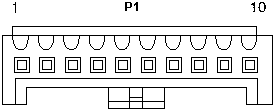
Power Supply Connector
P1

|
Pin
|
Signal
|
V Min
|
V Max.
|
|
1 2 3 4
|
+5 volts
|
+4.8
|
+5.25
|
|
5 6 7 8 10
|
Ground
|
|
|
|
9
|
+20 volts
|
+19.0
|
+21.0
|
Power Supply Connector
P2

|
Pin
|
Signal |
V Min. |
V Max |
|
1,2
|
+12 volts
|
+11.52
|
+12.6
|
|
3
|
Power Good
|
+4.0
|
+5.25
|
|
4
|
On/Off Signal
|
|
|
|
5
|
-12 volts
|
-10.92
|
-13.2
|
|
6,7
|
Ground
|
|
|
|
8
|
Global Signal
|
|
|
9595 Main Page
|